How To Connect An Ammeter And Voltmeter In A Circuit . an ammeter is connected in series while a voltmeter is connected in parallel. to study the dependence of current (i) on the potential difference (v) across a resistor, the correct way of connecting the ammeter. • an ideal ammeter has almost. the wiring schematic for an ammeter varies depending on the type of circuit and the specific ammeter being used. Created by david santopietro.watch the. understanding their basic principles of operation is crucial for accurate measurements and safe usage. learn about the instruments we use to measure voltage and current. Ammeters have low resistances and are placed in the. a voltmeter is connected in parallel with a device to measure its voltage, while an ammeter is connected in series with a. Ammeters measure the current through a resistor.
from www.allaboutcircuits.com
Ammeters have low resistances and are placed in the. Created by david santopietro.watch the. to study the dependence of current (i) on the potential difference (v) across a resistor, the correct way of connecting the ammeter. a voltmeter is connected in parallel with a device to measure its voltage, while an ammeter is connected in series with a. understanding their basic principles of operation is crucial for accurate measurements and safe usage. the wiring schematic for an ammeter varies depending on the type of circuit and the specific ammeter being used. • an ideal ammeter has almost. learn about the instruments we use to measure voltage and current. Ammeters measure the current through a resistor. an ammeter is connected in series while a voltmeter is connected in parallel.
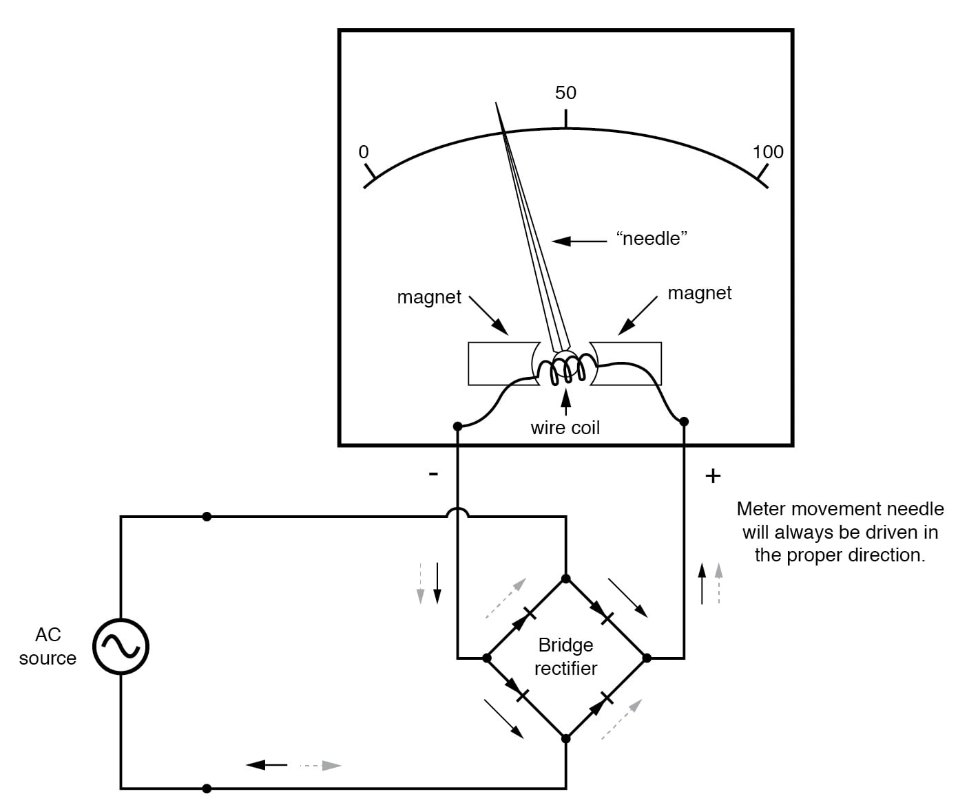
AC Voltmeters and Ammeters AC Metering Circuits Electronics Textbook
How To Connect An Ammeter And Voltmeter In A Circuit a voltmeter is connected in parallel with a device to measure its voltage, while an ammeter is connected in series with a. Created by david santopietro.watch the. the wiring schematic for an ammeter varies depending on the type of circuit and the specific ammeter being used. an ammeter is connected in series while a voltmeter is connected in parallel. a voltmeter is connected in parallel with a device to measure its voltage, while an ammeter is connected in series with a. understanding their basic principles of operation is crucial for accurate measurements and safe usage. Ammeters have low resistances and are placed in the. learn about the instruments we use to measure voltage and current. Ammeters measure the current through a resistor. • an ideal ammeter has almost. to study the dependence of current (i) on the potential difference (v) across a resistor, the correct way of connecting the ammeter.
From byjus.com
How is an ammeter connected in a circuit how is a voltmeter connected How To Connect An Ammeter And Voltmeter In A Circuit Created by david santopietro.watch the. to study the dependence of current (i) on the potential difference (v) across a resistor, the correct way of connecting the ammeter. understanding their basic principles of operation is crucial for accurate measurements and safe usage. Ammeters measure the current through a resistor. Ammeters have low resistances and are placed in the. Web. How To Connect An Ammeter And Voltmeter In A Circuit.
From www.youtube.com
what will happen if the voltmeter connected in series and the ammeter How To Connect An Ammeter And Voltmeter In A Circuit a voltmeter is connected in parallel with a device to measure its voltage, while an ammeter is connected in series with a. • an ideal ammeter has almost. understanding their basic principles of operation is crucial for accurate measurements and safe usage. an ammeter is connected in series while a voltmeter is connected in parallel. to. How To Connect An Ammeter And Voltmeter In A Circuit.
From schematicscolia.z13.web.core.windows.net
Schematic Diagram Of Ammeter How To Connect An Ammeter And Voltmeter In A Circuit learn about the instruments we use to measure voltage and current. Created by david santopietro.watch the. a voltmeter is connected in parallel with a device to measure its voltage, while an ammeter is connected in series with a. to study the dependence of current (i) on the potential difference (v) across a resistor, the correct way of. How To Connect An Ammeter And Voltmeter In A Circuit.
From wiremanualhillery.z4.web.core.windows.net
Digital Voltmeter And Ammeter Circuit Diagram How To Connect An Ammeter And Voltmeter In A Circuit to study the dependence of current (i) on the potential difference (v) across a resistor, the correct way of connecting the ammeter. a voltmeter is connected in parallel with a device to measure its voltage, while an ammeter is connected in series with a. the wiring schematic for an ammeter varies depending on the type of circuit. How To Connect An Ammeter And Voltmeter In A Circuit.
From schematicdiagramsaenger.z13.web.core.windows.net
Digital Ammeter Circuit Diagram How To Connect An Ammeter And Voltmeter In A Circuit to study the dependence of current (i) on the potential difference (v) across a resistor, the correct way of connecting the ammeter. • an ideal ammeter has almost. Ammeters measure the current through a resistor. understanding their basic principles of operation is crucial for accurate measurements and safe usage. Ammeters have low resistances and are placed in the.. How To Connect An Ammeter And Voltmeter In A Circuit.
From manuallibmelinda.z19.web.core.windows.net
How To Connect A Voltmeter To A Circuit How To Connect An Ammeter And Voltmeter In A Circuit an ammeter is connected in series while a voltmeter is connected in parallel. to study the dependence of current (i) on the potential difference (v) across a resistor, the correct way of connecting the ammeter. Ammeters measure the current through a resistor. learn about the instruments we use to measure voltage and current. understanding their basic. How To Connect An Ammeter And Voltmeter In A Circuit.
From www.youtube.com
Voltmeter Ampere Meter Connection Diagram । Engineers CommonRoom How To Connect An Ammeter And Voltmeter In A Circuit the wiring schematic for an ammeter varies depending on the type of circuit and the specific ammeter being used. • an ideal ammeter has almost. understanding their basic principles of operation is crucial for accurate measurements and safe usage. Ammeters measure the current through a resistor. learn about the instruments we use to measure voltage and current.. How To Connect An Ammeter And Voltmeter In A Circuit.
From wiring.ekocraft-appleleaf.com
How To Connect A Voltmeter In Parallel Circuit Wiring Diagram How To Connect An Ammeter And Voltmeter In A Circuit Created by david santopietro.watch the. understanding their basic principles of operation is crucial for accurate measurements and safe usage. to study the dependence of current (i) on the potential difference (v) across a resistor, the correct way of connecting the ammeter. an ammeter is connected in series while a voltmeter is connected in parallel. Ammeters measure the. How To Connect An Ammeter And Voltmeter In A Circuit.
From keystagewiki.com
Voltmeter Key Stage Wiki How To Connect An Ammeter And Voltmeter In A Circuit an ammeter is connected in series while a voltmeter is connected in parallel. Ammeters measure the current through a resistor. the wiring schematic for an ammeter varies depending on the type of circuit and the specific ammeter being used. understanding their basic principles of operation is crucial for accurate measurements and safe usage. • an ideal ammeter. How To Connect An Ammeter And Voltmeter In A Circuit.
From comparisoneureka39150.blogspot.com
⭐ Circuit Diagram With Ammeter And Voltmeter ⭐ How To Connect An Ammeter And Voltmeter In A Circuit • an ideal ammeter has almost. learn about the instruments we use to measure voltage and current. Created by david santopietro.watch the. Ammeters have low resistances and are placed in the. an ammeter is connected in series while a voltmeter is connected in parallel. the wiring schematic for an ammeter varies depending on the type of circuit. How To Connect An Ammeter And Voltmeter In A Circuit.
From courses.lumenlearning.com
Voltmeters and Ammeters Boundless Physics How To Connect An Ammeter And Voltmeter In A Circuit understanding their basic principles of operation is crucial for accurate measurements and safe usage. learn about the instruments we use to measure voltage and current. to study the dependence of current (i) on the potential difference (v) across a resistor, the correct way of connecting the ammeter. • an ideal ammeter has almost. Created by david santopietro.watch. How To Connect An Ammeter And Voltmeter In A Circuit.
From circuitenginefascio.z21.web.core.windows.net
How To Connect A Voltmeter And Ammeter How To Connect An Ammeter And Voltmeter In A Circuit Created by david santopietro.watch the. learn about the instruments we use to measure voltage and current. Ammeters have low resistances and are placed in the. an ammeter is connected in series while a voltmeter is connected in parallel. to study the dependence of current (i) on the potential difference (v) across a resistor, the correct way of. How To Connect An Ammeter And Voltmeter In A Circuit.
From www.almrsal.com
يوصل الأميتر في الدائرة الكهربائية على التوازي المرسال How To Connect An Ammeter And Voltmeter In A Circuit a voltmeter is connected in parallel with a device to measure its voltage, while an ammeter is connected in series with a. to study the dependence of current (i) on the potential difference (v) across a resistor, the correct way of connecting the ammeter. Created by david santopietro.watch the. understanding their basic principles of operation is crucial. How To Connect An Ammeter And Voltmeter In A Circuit.
From www.sarthaks.com
In the circuit shown here, the readings of the ammeter and voltmeter How To Connect An Ammeter And Voltmeter In A Circuit understanding their basic principles of operation is crucial for accurate measurements and safe usage. a voltmeter is connected in parallel with a device to measure its voltage, while an ammeter is connected in series with a. the wiring schematic for an ammeter varies depending on the type of circuit and the specific ammeter being used. to. How To Connect An Ammeter And Voltmeter In A Circuit.
From www.pcboard.ca
Dual Digital Voltmeter and Ammeter 0.28inch LED Displays How To Connect An Ammeter And Voltmeter In A Circuit Ammeters measure the current through a resistor. • an ideal ammeter has almost. learn about the instruments we use to measure voltage and current. a voltmeter is connected in parallel with a device to measure its voltage, while an ammeter is connected in series with a. understanding their basic principles of operation is crucial for accurate measurements. How To Connect An Ammeter And Voltmeter In A Circuit.
From guidediagramcirripedia.z21.web.core.windows.net
How To Connect Ammeter In Circuit How To Connect An Ammeter And Voltmeter In A Circuit Created by david santopietro.watch the. Ammeters have low resistances and are placed in the. the wiring schematic for an ammeter varies depending on the type of circuit and the specific ammeter being used. to study the dependence of current (i) on the potential difference (v) across a resistor, the correct way of connecting the ammeter. an ammeter. How To Connect An Ammeter And Voltmeter In A Circuit.
From www.allaboutcircuits.com
AC Voltmeters and Ammeters AC Metering Circuits Electronics Textbook How To Connect An Ammeter And Voltmeter In A Circuit • an ideal ammeter has almost. the wiring schematic for an ammeter varies depending on the type of circuit and the specific ammeter being used. Ammeters measure the current through a resistor. Ammeters have low resistances and are placed in the. an ammeter is connected in series while a voltmeter is connected in parallel. learn about the. How To Connect An Ammeter And Voltmeter In A Circuit.
From www.58pcba.com
How is the voltmeter and ammeter connected in a circuit? Technical How To Connect An Ammeter And Voltmeter In A Circuit to study the dependence of current (i) on the potential difference (v) across a resistor, the correct way of connecting the ammeter. • an ideal ammeter has almost. understanding their basic principles of operation is crucial for accurate measurements and safe usage. Ammeters have low resistances and are placed in the. Ammeters measure the current through a resistor.. How To Connect An Ammeter And Voltmeter In A Circuit.